
The Harris Hydraulics Laboratory at the University of Washington is a fully equipped laboratory for teaching, research and testing in marine energy, environmental fluid mechanics, and related topics. The laboratory is used by researchers from departments across campus, including Civil and Environmental Engineering, Applied Physics Laboratory, Mechanical Engineering and Oceanography. The three primary experimental areas of potential interest to marine energy R&D are:
Visualization Tank; and
Explore this page for more details of these experimental areas. If you’re interested in gaining access to use any of the Harris facilities, please reach out to testing@pmec.us with details or consider applying to the U.S. Department of Energy’s TEAMER program.

Alice C. Tyler Flume
The Alice C. Tyler flume is a free-surface water channel with independent control of flow speed, water depth, and water temperature. This allows the Reynolds and Froude numbers to be independently varied during turbine experiments. Turbulence intensity is relatively low (1-3%). The flume side walls and bottom are glass, providing optical access for flow diagnostics, including Laser Doppler Velocimetry (LDV) and Particle Image Velocimetry (PIV). Using existing instrumentation and data acquisition, cross-flow turbine rotors and axial-flow turbine blades can be easily tested.
+ Facility Description
- Open channel flume
- Dimensions: 4.6 m long, 0.76 m wide, 0.7 m high
- Open top, optical-quality glass side walls and base
- Dynamic depth: 30 - 60 cm
- Temperature: 10 – 35 oC
- Velocity: Up to 1.1 m/s (depends on dynamic depth and temperature)
- Turbulence intensity: 1-3% (depends on operating conditions)
+ Facility Instrumentation
- Nortek Vectrino Profiler (ADV) - 2 units
- Cabled and fixed heads
- Maximum sampling rate of 200 Hz
- Nortek Vector (ADV)
- Maximum sampling rate of 64 Hz
- Particle Image Velocimetry
- Planar velocity measurement (x,y velocity) with automated z-axis motion
- 2x Vision Research Phantom v641 high-speed cameras, 2560x1600 pixels 10-1450 fps at full resolution
- Dual-cavity Terra PIV laser. 527 nm wavelength, 0.1-10 kHz pulse repetition
- Example Field of View

- TSI and LaVision post-processing software
- Stereo velocity measurement (x,y,z velocity)
- Positioning gantry
- Mounted on top of flume test section – can be used to profile ADVs in x, y, and z directions
- Cross-flow turbine test rig – rotor characterization

- 6-axis load cells on both ends of vertically oriented rotor (ATI Mini45 and ATI Mini40)
- Servomotor for torque, velocity, or position control
- Force, torque, and rotation data acquisition at 1 kHz
- Recommended test article size < 17 cm diameter x < 25 cm height
- Axial-flow turbine test rig – blade characterization

- 6-axis load cells at blade root and in nacelle
- Variable pitch actuation
- Force, torque, and rotation data acquisition at 100 Hz
- Up to 45-cm blade span
+ Areas of Expertise
- Cross-flow and axial-flow turbine performance and load characterization
- Experimental design to maintain constant Reynolds number, Froude number, and flow confinement
- Flow-field quantification in and around cross-flow turbine rotors


Visualization Tank
The oscillation visualization tank is a water-filled acrylic cube with an open top. A linear oscillator can be used to drive test articles, such as heave plates, through strokes of controllable amplitude and period. During oscillation, a submersible (IP 68) 6-axis load cell can measure forces and torques on a test article, while position is tracked by an encoder. From this, phase-dependent and phase-independent estimates of inertial and drag forces can be resolved. The acrylic walls allow optical access from all sides for qualitative and quantitative flow visualization. To date, this facility has been used primarily to study heave plate hydrodynamics.
+ Facility Description
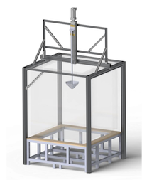
- Optical-quality acrylic cube with open top
- 1.27 m long, 1.27 m wide, 1.45 m high
- Water depth: 0.1 – 1.25 m
- Ambient temperature, quiescent water
+ Facility Instrumentation
- Linear actuator with 532 mm stroke
- 6-axis submersible load cells (ATI Nano25, ATI Mini40, and ATI Nano17)
- Dye injection for coherent structure visualization
+ Areas of Expertise
- Hydrodynamic force decomposition (drag and inertia) for bodies oscillating


Washington Air-Sea Interaction Research Facility (WASIRF)
WASIRF is a wind-wave-current tank facility formerly located at the NASA Wallops Island Flight Facility. WASIRF is a laboratory testing tank designed to investigate wind-wave-current interactions.
+ Facility Description

- Open channel flume capable of producing waves, winds and currents
- 12 m long, 0.91 m wide, 1.22 m high
- Water depth: up to 75 cm
- Wave conditions: _H_ < 0.1 m, 0.1 s < _T_ < 1 s
- 2D waves with absorption beach
- Programable for regular and random waves and focused wave breaking
- Wind < 20 m/s
- Currents < 1 m/s (depending on depth)
- Ability to simulataneously generate waves, currents, and wind
- Temperature regulation of water and air
- Optical-quality glass on one face and a portion of the bottom, aluminum face and bottom
- Removable false bottom
+ Facility Instrumentation
- Capacitive wave gauges (5)
- Visible and IR cameras
- Nortek Vectrino ADV
+ Areas of Expertise
- Breaking wave dynamics and turbulence
- Coming in 2022: Oscillating surge wave energy converter test article
If you’re interested in gaining access to use any of the Harris facilities, please reach out to testing@pmec.us with details or consider applying to the U.S. Department of Energy’s TEAMER program.
Read more from the UW Department of Civil Engineering’s Harris Hydraulics Laboratory facility page.